Safety Assurance
Summary
-
DIVP® has been promoting research and development in collaboration with industry, academia, and government as part of the SIP-adus project. We hope that the novelty of the series of models (environment, radio wave propagation, and sensors) can be utilized to ensure connectivity with other simulators, and that it will become a fundamental technology for efficient and wide-ranging verification of the safety of automated driving, which is becoming increasingly complex. All the members of the DIVP® sincerely hope that the virtual space technology, which is an elaborate digital twin of the real environment, will improve consumer acceptance of the safety of automated driving and contribute to the promotion of the social implementation of automated driving.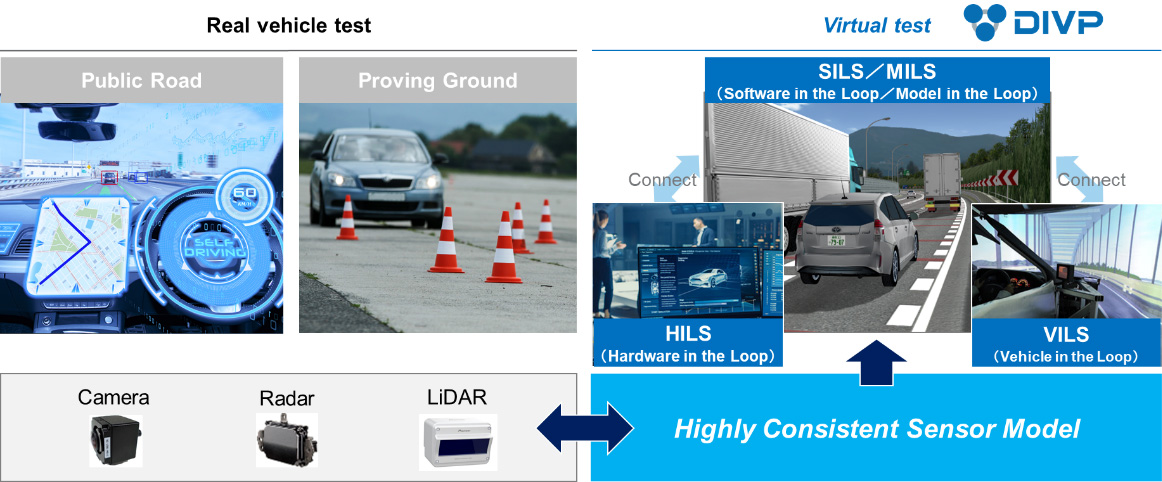
- Introduction
- DIVP® Overview
2.1 Constructing highly consistent sensor models with real phenomena based
(1) Camera
(2) Millimeter wave radar
(3) Lidar
(4) Environmental model - Standardization and international collaborations
-
Member of DIVP® consortium (as of 2021-april)
-
Theme Leader
Hideo Inoue, Kanagawa Institute of Technology
(Leading development of DIVP® and DIVP® consortium)Industry
DENSO Corporation/Hitachi Astemo, Ltd./MITSUBISHI PRECISION CO.,LTD./Nihon Unisys, Ltd./Pioneer Smart Sensing Innovations Corporation/ SOKEN,INC./SOLIZE Corporation/Sony Semiconductor Solutions Corporation/TOYOTA TECHNICAL DEVELOPMENT CORPORATION
Academia
Kanagawa Institute of Technology/ Ritsumeikan University/ TOYOTA TECHNOLOGICAL INSTITUTE
-
Standardization & International collaboration
-
Hideaki Sato, Toyota motor corporation (Promoting activities of international collaboration for safety assurance and supporting DIVP® consortium from outside)
1. Introduction
This part describes the development of the "Driving Intelligence Validation Platform (DIVP®)" project, which has been funded by Strategic Innovation Program (SIP) the 2nd phase of SIP-Automated Driving for Universal Services. And the development status of the project will be introduced.
The current reliability and safety validation of automated driving vehicles relies on the actual driving performance validation, which requires a huge amount of resources (human resource, materials, cost, and time). In addition, it is difficult to verify the physical limitation of sensors as environmental monitoring functionality, such as cameras, radars, and Lidars, which deal with the driving environment of the real world, and it is difficult to say to what extent safety can be guaranteed (How safe is safe enough?). Based on the above background, in this DIVP® project, we are constructing a validation platform in a virtual space characterized by a series of "driving environment objects – electromagnetic wave propagations - sensors" models that are highly consistent with real phenomena. This is intended to enable precise and efficient safety assurance for automated driving under a wide range of environmental scenarios (Fig. 1).
Fig. 1 Features of DIVP® high consistency sensor modeling with real phenomena
The DIVP® consortium is established by 12 organizations from industry and academia, including sensor manufacturers, software companies, and universities (Fig.2). In addition, DIVP® is collaborating with the SAKURA project promoted by JAMA and JARI to develop a safety validation environment for automated driving and to contribute to global standardization.
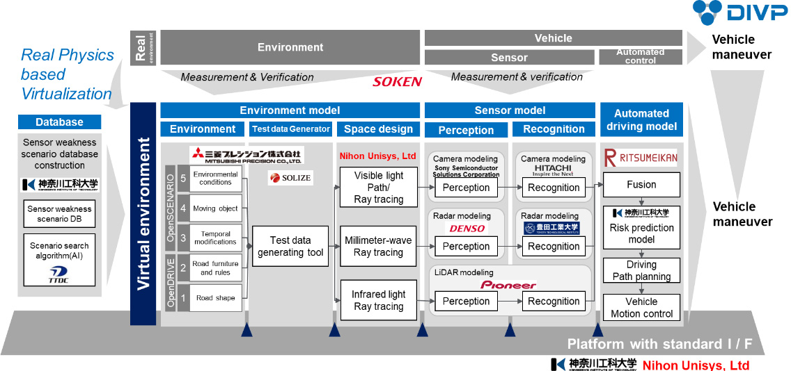
Fig. 2 DIVP® project design
2. DIVP® Overview
2.1 Constructing highly consistent sensor models with real phenomena based
Unlike ordinary vehicle component models, sensors that recognize the environment conditions play a functional role in connecting driving environment models and automatic driving control. In general simulators, the main focus is on evaluating whether the system control works correctly, and many sensing models are based on so-called ground truth models, that is to say a functional model. As mentioned earlier, in order to guarantee the safety of automated driving vehicle, it is necessary to understand the strengths and weaknesses (limitations) of each surrounding monitoring sensors, and to improve the system design, sensors, and perceptual recognition algorithms. However, it is difficult to reflect the weaknesses of the sensors in the simulation models because the functional sensor model does not reflect the verification results of the spatial propagation of electromagnetic waves. In this paper, we present a spatial propagation model of the ray tracing system as a physical based modeling.
We have developed a spatial propagation model of the ray tracing system based on the reflection characteristics (retro reflection, diffusion, specular reflection, etc.) and transmission characteristics of the electromagnetic waves, visible light for camera, millimeter wave for Radar and near-infrared light for Lidar, and also captured the physical phenomena that change due to the influence of the surrounding environment such as rain, fog, and ambient illumination. The unique feature of this model is that it reflects the spatial propagation characteristics view from the sensors in a series of models based on the electromagnetic wave principle of "driving environment objects – electromagnetic wave propagations - sensors" as perception models (Fig. 3). Specific examples are shown below.
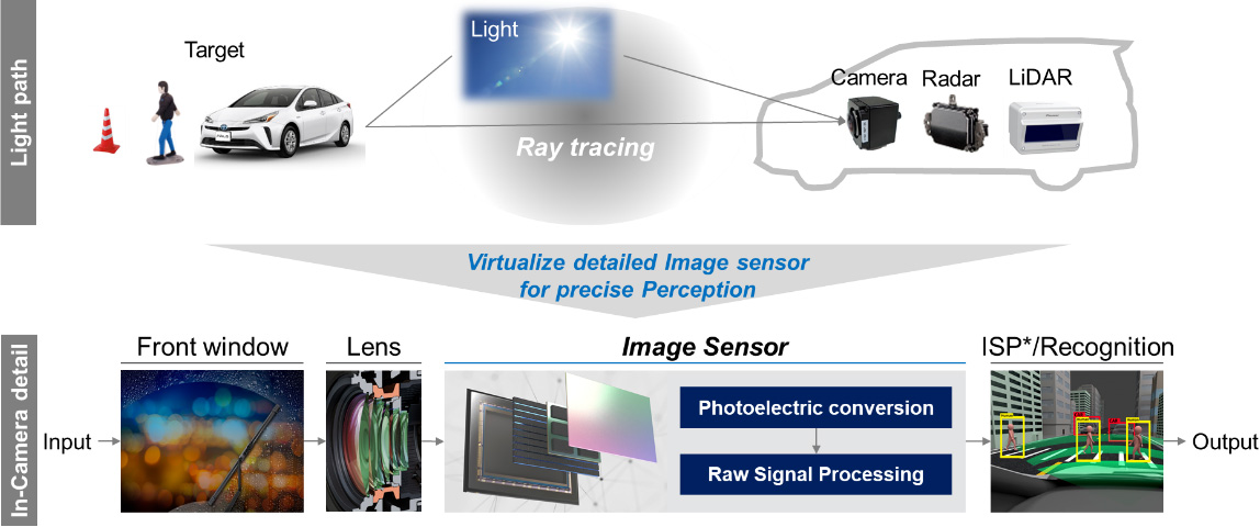
Fig. 3 Sensor modeling strategy
(1) Camera
The camera model simulates the spectral characteristics that are input to semiconductors such as CMOS, rather than the RGB is human eyes friendly. The sunlight is formulated as a sky model, which can simulate a precise sunlight source with the input of time, latitude and longitude.
As shown in Fig. 4, the reflection characteristics are defined on the objects to create a realistic simulation image.
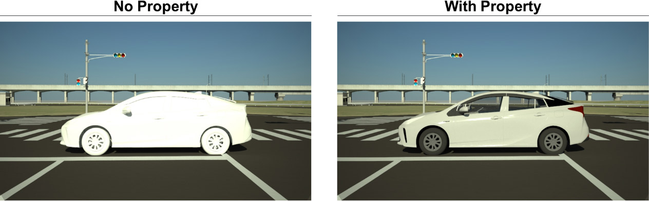
Fig. 4 Reflection Property definition on the objects
Fig. 5 also shows that the simulation verifies that the HDR (High Dynamic Range) camera model can provide sufficient visibility for recognition even in the dark condition in the tunnel, weak visible light with intense backlight at the approaching exit.
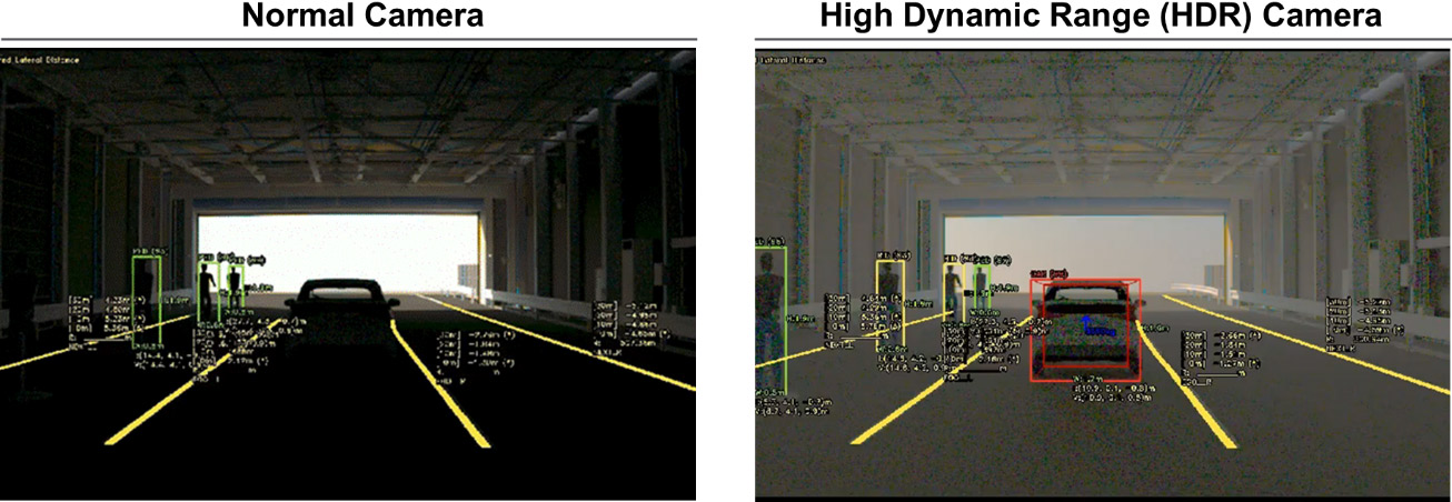
Fig. 5 Camera validation ability potential
(2) Millimeter wave radar
Radar is the most difficult sensor for modeling. Three reflection models are defined and used according to the behavior of radio waves at reflective targets. The PO approximation (Physical Optics) is used as the scatterer model for small objects such as cars and people, while the Geometric Optics approximation is used for large objects such as buildings and road surfaces as the reflector model. In addition, RCS (Radar Cross-Section) model is used to shorten the analysis time, which is defined for each object in advance, and assign them to the objects in a combined scenario. Figure 6 shows a scene of a vehicle passing between 2-cars as an example of sensor weakness.
It reproduces the sensing weakness scene that the low-resolution radar in azimuth does not provide perceptual output at the correct location and shows that this can be improved with higher resolution.
-
Lower resolution
-
Higher resolution
Fig. 6 Radar validation ability
(3) Lidar
Laser light is a relatively easier to modeling due to its directivity feature. Figure 7 shows a 360° scanning Lidar model. It is possible to evaluate environmental disturbances such as background light.
Fig. 7 Lidar simulation output
(4) Environmental model
The six-level classification of driving environment scenarios defined by Pegasus project in Europe. Sensing weakness validation is mostly rely on the environmental conditions and needs physical characteristics owned object models such as reflection, transmission, and attenuation of electromagnetic waves (Fig. 8, Fig. 9a, 9b, 9c). The skylight model, which models’ sunlight, is effective for evaluating sensing weakness scenarios such as backlight, because it can create a virtual space with good reproducibility of how the sunlight source hits the object by determining the time of day and the latitude and longitude of the object (Fig. 9a).
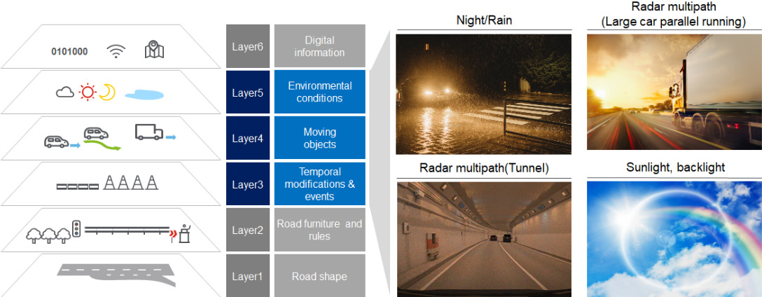
Fig. 8 Environmental modeling
Fig. 9a Skylight model
Fig. 9b Light model of the Metropolitan Expressway tunnel
Fig. 9c Rain adhesion model on windshield
2.2. Contribution to safety assessment
It is still an issue to what extent safety assessment scenarios should be conducted. However, if the conditions can be set in a virtual space with good reproducibility, the efficiency of validation will be greatly improved. In this project, we have set two milestones of scenario package: (1) assessment of NCAP, etc., and (2) validation of the actual traffic environment by modeling the demonstration community in Odaiba urban area and Tokyo metro C1 highway, enable to validate sensing weakness conditions. We are currently working on a series of "driving environment objects – electromagnetic wave propagations - sensors" perception models. It is necessary to define a virtual space as unit, which can be called a package scenario according to the purpose, and to improve the level of reliable safety assessment in this scenario package unit.
(1) Application to assessment validation such as NCAP
In the case of advanced safety systems with automated driving functions such as LKS (Lane Keeping Assis/ACC (Adaptive Cruise Control), ALKS (Automated Lane Keeping System), etc., validation protocols are defined in detail by Euro-NCAP, J-NCAP, etc. Although there are some differences depending on the traffic accident situation in each country, protocols that reflect the accident situation such as pedestrians, bicycles, right and left turns at intersections, and scenarios such as cut-in and cut-out in automated driving ALKS are important. In DIVP®, each assessment scenario is modeled sequentially. As an example, Fig. 10 shows a simulation of a pedestrian ejection scenario from the shade of a parked car with a sensor model. Such scenarios, which can be called "Virtual Proving Ground", can be extended to system validations that consider the effects of the environment such as rain, fog, and westering sun in a virtual space.
-
ABE Pedestrain crossing
-
Camera output
-
LiDAR output
Fig. 10 Eur-NCAP Pedestrian crossing
(2) Application to the validation of the real environment "Odaiba and C1 highway"
As the next scenario package, we are challenging to construct an environmental model of the Odaiba and C1 highway area, which is a mecca for automated vehicle demonstrations. In this virtual space, real environmental factors (driving environment, road, land, dynamic objects, weather, etc.) are combined to validate the sensor weakness scenario (Fig. 11). In collaboration with other SIP automated driving demonstration projects, the sensor recognition malfunction data (location, video, recognition output, etc.) generated in this realistic environment can be fed into the DIVP® simulator and sublimated into a virtual environment that can be evaluated by more users as Virtual Community Ground. For example, the road surface in front of the Odaiba Telecom Sensor was painted with a thermal barrier, and as a result, the reflection characteristics of the asphalt and the white line were similar, which made it difficult for Lidar to detect the white line, and this was reflected in the simulation model (Fig. 12). In this way, it is possible to collaborate with other automated driving projects, which is an effective framework unique to SIP-adus.
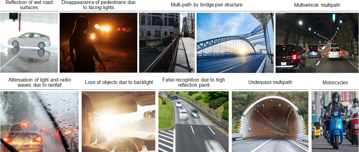
Fig. 11 Sensing weakness scenario examples
-
Camera simulation
-
Lidar simulation
Fig. 12 A Lidar model at a heart barrier painted road surface as sensing weakness scenarios (at Daiba station of Odaiba area)
3. Standardization and international collaborations
(1) Japan-Germany collaboration VIVID project
The VIVALDI project in Germany aims to contribute to the safety validation of automated driving based on sensor modeling, which is in line with the aims of DIVP®. In this context, VIVAVDI (Germany) and DIVP® (Japan) started the collaborative project "VIVID" in October 2020 based on the framework of the collaboration between SIP-adus of the Japanese Cabinet Office and the German Federal Ministry of Education and Research (BMBF). Through this project, an automated driving safety validation system and interface standardization are being promoted.
(2) Participation in ASAM, an international standards organization (Germany)
ASAM (Association Standardization of Automation and Measuring Systems) is engaged in a wide range of standardization activities related to automated driving. As DIVP, we are participating in the Open Drive/Open Scenario, OSI (Open Simulation Interface), and other working groups, and are proposing perceptual interfaces and others.
(3) Joint white paper by SAKURA, SIP-adus and HEADSTART
The HEADSTART project (Harmonised European Solutions for Testing Automated Road Transport) is the European project under Horizon 2020 and aims to define testing and validation procedures of Connected and Automated Driving functions. And the SAKURA project (Safety Assurance KUdos for Reliable Autonomous vehicles) is the Japanese project funded by the Ministry of Economy, Trade and Industry (METI), and develops the scenario-based safety assurance methodologies and a scenario database linked to the SIP-adus DIVP. In December 2021, SAKURA, SIP-adus, and HEADSTART projects jointly published the white paper titled “towards the harmonization of safety assessment methods of automated driving”.